this post was submitted on 15 Oct 2024
29 points (96.8% liked)
FreeCAD
952 readers
1 users here now
Your own 3D parametric modeler.
FreeCAD is an open-source parametric 3D modeler made primarily to design real-life objects of any size. Parametric modeling allows you to easily modify your design by going back into your model history and changing its parameters.
founded 2 years ago
MODERATORS
you are viewing a single comment's thread
view the rest of the comments
view the rest of the comments
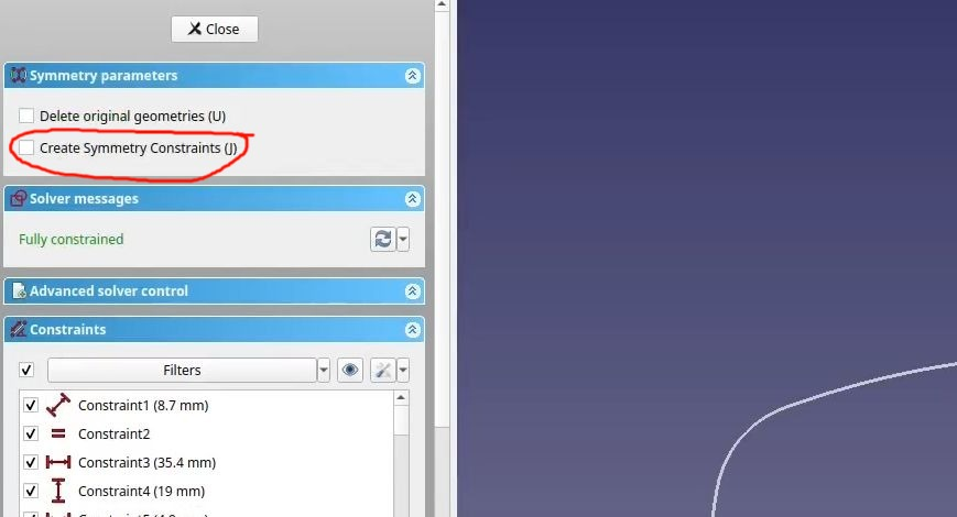
You didn't select "Create Symmetry Constraints". I'm not sure if it will solve the issue completely, but it will probably make some difference.
One thing I see that may come back to bite you later: You can create sketches that make multiple bodies when padded, but I'm not sure why you would want to with the example in this video. If the sketch is two identical bodies mirrored across an X/Y/Z plane use the part design mirror feature and offset the sketch's attachment not the geometry in the sketch. It works better for that and keeps your sketches simpler, and you get to use symmetry for one side of the two things you are making because the origin will be in the center of one of the objects.
Sketches where the origin of the sketch isn't the approximate center of a single closed wire are annoying later if you want to reference them in other features or sketches.
Are you making sunglasses? 😎
Oh...
Damn I feel stupid. I totally missed that somehow.
Thanks a lot, you rock! I learned something new today. I guess it was worth asking the question after all 🙂
No, I'm making regular frames for a friend because he saw the ones I made for myself a couple days ago and he asked whether I could print him new frames to reuse his old lenses.
I just used that sketch for the example.
Ah, I see. I imagined your use of that sketch differently. Looks good!